PowerClerk Support Center
- Project Pages
- Program Design Menu
-
- Automations
- Channels
- Communications
- Connections
- Content Library
- Custom API IDs
- Data Fields
- Deadlines
-
- Questions to ask yourself
- Locating the Deadlines feature
- What are Deadlines
- How to Create a Deadline
- Deadline Automation Action Rules
- Utilizing Project Admin Page for Deadlines
- Communication Templates for Deadlines
- Deadline Set/Satisfy Options
- Program-Wide Deadline Actions
- Reporting on Deadlines
- Deadlines in Project List Columns
- FAQs
- Document Templates
- eSignature Envelopes
-
- Questions to Ask
- Locating the eSignature Feature
- What are eSignature Envelopes?
- eSignature Checklist: The Prerequisites to create a new Envelope
- How to set up Advanced eSignature Envelopes Step-by-Step
- How to add an eSignature Envelope to a form
- eSignature Automation Trigger
- Viewing Completed eSignature Envelopes
- Resending eSignature Notifications
- Canceling eSignatures
- FAQs
- Forms
-
- Questions to ask yourself
- Locating the Forms feature
- How to create and edit Forms
- Adding data fields
- Form Versions and Draft Forms
- Configuring Forms
- Form Field Elements
- Field Properties
- Conditional Visibility
- Sensitive Data Fields
- Location Form Element
- Address Autocomplete
- Exporting a Form to Excel
- VersaForms
- FAQs
- Formulas and Calculated Fields
- Front Page
- Incentive Design
- Milestones
- Project List Columns
- Project Summary
- Project Views
- Roles
- Themes
- Workflow
- Admin Menu
- Tools Menu
-
- My Account
-
- Questions to Ask
- Locating the My Account feature
- How to use the My Account feature
- Lockouts and Password Resets
- Setting up Multi-Factor Authentication
- Missing, lost, or stolen mobile devices: resetting Multi-Factor Authentication
- Disabling Multi-Factor Authentication
- Recovery Guidelines for MFA Administrators
- FAQs
- FormSense
- Grant Access
- Integration Guides & API
- PowerClerk Video Guides
-
- Setting up Roll-up Reports
- New User Video Guide
- Configuring Forms
- Roles and User Administration
- Setting up Business Days
- Formulas and Advanced Visibility Rules
- Visualize Workflows
- Dashboards
- FormSense
- Milestones
- ArcGIS
- Project Summary
- Automation with Formulas in Action Rules
- API
- Edit Forms - Tutorial #1
- SFTP Automatic Data Import
- Calculated Fields
- Web Connector Setup
- Edit Forms - Tutorial #2
- Build A Formula
- Help Articles
- PowerClerk Program Launch
- PowerClerk User Group Sessions (UGS)
- Learning Management System (LMS)
- Join us for Reflow!
- NEW: PowerClerk Certifications
Integration Guide 002: How to configure Electric Power Research Institute’s (EPRI) DRIVE Connect software with PowerClerk
Use DRIVE Connect to expedite the interconnection screening process, automate hosting capacity analysis, and produce tangible screening results that are useful to distribution planning engineers.

Questions to ask yourself about the DRIVE Connect integration:
What data do I want to pull out of my hosting capacity analysis to show in PowerClerk?
What data collection do I want to automate to represent the current and planned DERs on a given circuit’s queue?
Where is the energy source, capacity, kVAR, circuit, bus/node data located within the PowerClerk Workflow?
Where does my utility’s network and circuit information live (in GIS or in the distribution model)?
*Note: A Clean Power Research Administrator must first enable the Custom API ID feature in your program to allow DRIVE Connect to work in PowerClerk.
Difficulty: Advanced.
Duration to review this Integration Guide: ~60 minutes.
What you will learn in this integration guide:
- How to configure DRIVE Connect with PowerClerk Forms
- How to configure the PowerClerk Workflow to accept the DRIVE Connect integration
- Setting up Custom API IDs
- DRIVE Connect-specific FAQs
Introduction
There are (8) main components required to set up the EPRI DRIVE Connect integration in PowerClerk:
These components allow DRIVE Connect to find projects in the queue and submit the DRIVE results, among other things.
One planning model process that is not covered by this document is determining which circuit and node the proposed DER would be located on in an interconnection application.
If you would like to receive more information on the EPRI DRIVE Connect integration with PowerClerk or have an inquiry on how to integrate an external resource with your program, please let us know.
1. Installation of DRIVE Connect
System requirements
- Required Operating Systems: Windows 7 or Windows 10
- PowerClerk
- DRIVE version 2.0
- Text Editor (e.g. Notepad)
- Please note: Operating System Administrative rights are required to save changes to the DRIVE Connect configuration file.
Installation of the Software
In order to install the module, you will need to run the DRIVE Connect Setup installer and follow these steps:
- When the installer launches read through the license agreements and click the Next button.
- Select the desired installation folder. The default location is suitable for installation, however, other locations can be used.
- Confirm the installation by clicking on the Next button.
Analysis Directory and DRIVE Batch File
DRIVE Connect uses the batch run capabilities of DRIVE in order to automate a hosting capacity analysis. When operated in batch mode, DRIVE uses the input files for all feeders that exist in a specified directory. In order to use DRIVE Connect, a directory that does not contain any DRIVE input files is required. Create a new directory called “Interconnection_Requests” in a location that has write privileges without administrator rights (e.g. C:\Documents\Interconnection_Requests). Perform the following steps to configure the batch script for DRIVE Connect:
- In the Integration Guide folder of the DRIVE installation directory, open ExampleBatchProcess.bat in a plain text editor like Notepad. Edit the first string to identify the path to DRIVE.exe. Edit the second string to identify the path to the Interconnection_Requests directory. Example:
"C:\DRIVE\DRIVE.exe" "C:\DRIVE\Integration_Guide" - Save this file in the Interconnection_Requests directory as DRIVEConnectBatch.bat.
- Copy the BatchSettings.txt file from the DRIVE Integration Guide folder into the newly created directory. These settings will be the settings used in the automated analysis. The BatchSettings.txt file can be manually updated by the user, but the file must be named BatchSettings.txt.
- Verify that the batch script is specified correctly:
- STEP 1: Copy a set of DRIVE input files from the DRIVE Integration Guide folder (_buses.csv,
_data.csv, _reg.csv, _sections.csv) for a single feeder into the Interconnection_Requests directory. - STEP 2: Run the batch script. If the batch script is specified correctly the DRIVE hosting capacity results will be populated in the Interconnection_Requests directory.
- STEP 3: Delete the DRIVE input files and DRIVE hosting capacity results files from the Interconnection_Requests directory.
- STEP 1: Copy a set of DRIVE input files from the DRIVE Integration Guide folder (_buses.csv,
Configuration file
The DRIVE Connect installer creates the DRIVE Connect.exe.config configuration file that needs to be configured prior to starting the DRIVE Connect service. This file is in the installation directory and should be opened with a plain text editor such as notepad or notepad++. Administrator privileges are required to save changes to this file if installed in the C:\Program Files or C:\Program Files (x86) directories. The following steps need to be followed to fully configure the DRIVE Connect.exe.config file:
- STEP 1: Specify the path, including the file name, to the location where the DRIVE Connect service log will be stored. It is recommended that this log file be stored in the Interconnection_Requests directory that was previously created. The default path and file name is C:\DRIVEConnect.log, declared on line 12 of the DRIVE Connect.exe.config file. The new path and file name should remain in quotes:
<file value="C:\users\pnhe001\Documents\Projects\SHINES_DEMO\Interconnection_Requests\DRIVEConnect.log"/> - STEP 2: Set the run interval to determine how often DRIVE Connect checks for new projects to analyze in PowerClerk. This value is specified by the key RunInterval on line 25 and should remain in quotes:
<add key="RunInterval" value="900"/> - STEP 3: Specify the URL of the users PowerClerk implementation. This value is specified by the key PClerkBaseURL on line 27 and should remain in quotes. The best practice is to copy the URL directly from an internet browser to avoid typos:
<add key="PClerkBaseURL" value="https://api.cleanpowerdemo.com/PCITrial/Services.svc/v1"/> - STEP 4: 4) Enter the PowerClerk username of an administrator to the users PowerClerk implementation. This name is specified by the key PClerkUserName on line 29 and should remain in quotes. Changes in project statuses created by DRIVE Connect will reflect this users name:
<add key="PClerkUserName" value="your_name@your_company.com"/> - STEP 5: Enter the PowerClerk password associated with the username specified in step 3. The password is specified by the key PClerkPassword on line 30 and should remain in quotes:
<add key="PClerkPassword" value="notmyactualpassword"/> - STEP 6: Specify the PowerClerk API Key using the key PClerkApiKey on line 31 and keep the value in quotes:
<add key="PClerkApiKey" value="c72**7****ih9"/> - STEP 7: Specify the PowerClerk agency ID using the key PClerkAgencyID on line 32 and keep the value in quotes:
<add key="PClerkAgencyID" value="U42BHSCWD9X4"/> - STEP 8: Enter the full path to the directory containing the DRIVE input files; these are the sets of four .csv files that are extracted for each feeder when using the Model Interface python scripts. This path is specified by the key DRIVEInputFile Path on line 34 and should be kept in quotes. The DRIVE input files for any feeder that will be analyzed with DRIVE Connect must be available in this directory:
<add key="DRIVEInputFilePath" value="C:\users\pnhe001\Documents\Projects\SHINES_DEMO"/> - STEP 9: Enter the full path to the DRIVEConnectBatch.bat, including the name of the batch script, that was described in the previous section. This path is specified by the key DRIVEScriptPath on line 36 and should remain in quotes:
<add key="DRIVEScriptPath"<br>value="C:\Users\pnhe001\Documents\Projects\SHINES_DEMO\Interconnection_Requests\SHINES_DRIVE_BATCH.bat"/> - STEP 10: Enter the full path to the Interconnection_Requests output directory that was created in the previous section. This path is specified by the key DRIVEOutputFile Path on line 38 and should remain in quotes:
<add key="DRIVEOutputFilePath" value="C:\users\pnhe001\Documents\Projects\SHINES_DEMO\Interconnection_Requests"/> - STEP 11: Enter the DRIVE impact factors that are critical to the user when post-processing the hosting capacity results. These values are specified by the key DRIVEImpactFactorColumns on line 42 and should remain in quotes, separated by a single comma and no spaces. DRIVE calculates the hosting capacity for all impact factors, but DRIVE Connect only checks the specified impact factors when returning the Within Hosting Capacity metric. Best practice is to copy the impact factor name from the header of the __HC Summary – Centralized DER – XX.csv file without the “– min” or “– max” suffix:
<add key="DRIVEImpactFactorColumns" value="Primary Over-Voltage,Regulator Voltage Deviation"/> - STEP 12: Enter the PowerClerk statuses of other projects that should be considered with the current project regardless of status-change timestamp. These statuses are specified by the key DRIVEAnalysisStatus1 on line 45 and should match the PowerClerk status exactly. The statuses should remain in quotes and be separated by a single comma and no spaces. If no other statuses will be considered in the analysis the field can be left blank, but the open and closed quotation marks should remain:
<add key="DRIVEAnalysisStatus1" value="Permission to Operate"/> - STEP 13: Enter the PowerClerk statuses of other projects that should be considered with the current project only if the status-change timestamp is earlier than that of the current project. These statuses are specified by the key DRIVEAnalysisStatus2 on line 47 and should match the PowerClerk status exactly. The statuses should remain in quotes and be separated by a single comma and no spaces. If no other statuses will be considered in the analysis the field can be left blank, but the open and closed quotation marks should remain:
<add key="DRIVEAnalysisStatus2" value="Application Under Review"/>
Do not change any other fields in the DRIVEConnectService.exe.config file. Save this file in its current location. Administrator privileges may be required to save this file depending on the installation directory.
2. Configuring the Interconnection Application Form
The Interconnection Application Form must contain the following fields:
- DG Energy Source (Drop-down List form element)
- Total Generator Nameplate Capacity (AC-kW) (Decimal form element)
- Desired Operating kVAR (Decimal form element)
The first field that needs to be created is Distributed Generation (DG) Energy Srouce, which is a Drop-down List form element configured with various types of Distributed Energy Resources (DERs) which your specific program accepts. Any DER type can be included in the Drop-down List form element if those types are 1.) composed of a single word, 2.) represented in the DRIVE DER.txt file found in the DRIVE installation directory, and 3.) capitalized. If, for example, energy storage is included in the Drop-down List form element, all letters in the name must be capitalized (e.g. ENERGY STORAGE).

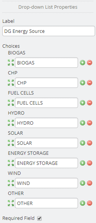
The DRIVE screening service will report the DER type in the designated location of the DRIVE input files using the name exactly as specified in the PowerClerk DG Energy Source Drop-down List form element, except for ENERGY STORAGE which will be represented as STORAGE.
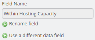
Note that while the Label on each form element can be left to the program designer’s discretion, the data field form element Field Name must match the descriptions in this integration guide.
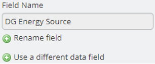
The second field that needs to be created is Total Generator Nameplate Capacity, which is a decimal field that describes the real power (kW) output of the DER in the application, including any de-rating due to altitude, etc.

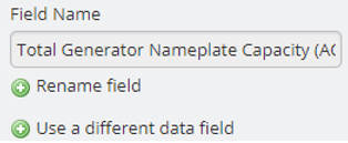
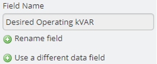
The third and final field that needs to be created is the Desired Operating kVAR, which is a decimal field that describes the normal reactive power capability (kVAR) of the DER in the application. The DRIVE Connect integration considers positive (>0) values of kVAR to be inductive and negative (<0) values of kVAR to be capacitive. Desired Operating kVAR is assumed to be fixed and is representative of the reactive component of the maximum apparent power (kVA) output.

3. Configuring the Engineering Review Project Data Form
The Engineering Review Project Data Form must contain the following fields:
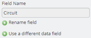
- Circuit (Single Line Text form element)
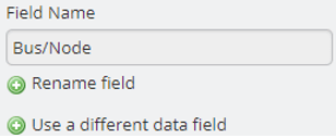
- Bus/Node (Single Line Text form element)
- DG Energy Source (Drop-down List form element)
- Total Generator Nameplate Capacity (AC-kW) (Decimal form element)
- Desired Operating kVAR (Decimal form element)
In addition to being configured according to this document, these fields must be populated for a given project prior to changing the project status to DRIVE Analysis Requested.
Note that while the Label on each form element can be left to the program designer’s discretion, the data field form element Field Name must match the descriptions in this integration guide.
The first field that needs to be created is Circuit, which is a Single Line Text form element and must be populated with a circuit name which matches the name of the appropriate circuit in the DRIVE input files. This information must be populated prior to switching the application to the DRIVE Analysis Requested Workflow Status.

The second field that needs to be created is Bus/Node, which is a Single Line Text form element, and must be populated with a node name that matches the name of the appropriate node in the DRIVE input files. This information must be populated prior to switching the application to the DRIVE Analysis Requested Workflow Status.

The third, fourth, and fifth, DER Energy Source, Total Generator Nameplate Capacity (AC-kW), and Desired Operating kVAR should be configured in the Engineering Review Project Details Form with the same properties as described for the Interconnection Application form.
4. Configuring the DRIVE Analysis Results Form
The DRIVE Analysis Results Form is used by the DRIVE screen service to return the results of the hosting capacity analysis and must contain the following fields:
- Within Hosting Capacity (Drop-down List form element)
- Impacts Exceeded (Single Line Text form element)
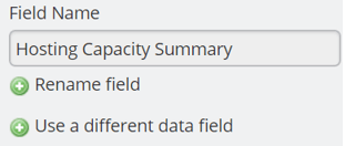
- Hosting Capacity Summary (Attachment form element)
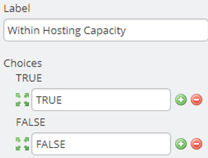
The first field that needs to be created is Within Hosting Capacity, which is a Drop-down List form element.

The available choices in the drop-down list are required to be configured with TRUE and FALSE in all caps.
The second field that needs to be created is Impacts Exceeded, which is a Single Line Text form element.

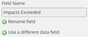
The third and final field that needs to be created is Hosting Capacity Summary, which is an Attachment form element.

5. Workflow Configuration
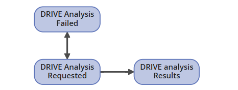
In order to automate the hosting capacity analysis using DRIVE connect it is necessary to configure three new statuses in the PowerClerk workflow for each available program. The three statuses can be integrated at any point in the workflow after an application is submitted and before the application/project is granted permission to construct. The three statuses are:
- DRIVE Analysis Requested
- DRIVE Analysis Results
- DRIVE Analysis Failed
Any status in the workflow can have a transition to DRIVE Analysis Requested, and DRIVE Analysis Results can have a transition to any status in the workflow. As seen in Figure 20, below, the Workflow is required that DRIVE Analysis Requested have transitions to both DRIVE Analysis Failed, and DRIVE Analysis Results. It is also required that DRIVE Analysis Failed have a transition to DRIVE Analysis Requested.
6. Custom API IDs
The DRIVE Connect integration needs to interact with Clean Power Research’s API in order to exchange data. Doing so requires Custom API IDs to be configured in PowerClerk. Note that a CPR Administrator must first enable the Custom API IDs within your program before it becomes available to you on the Program Design menu:
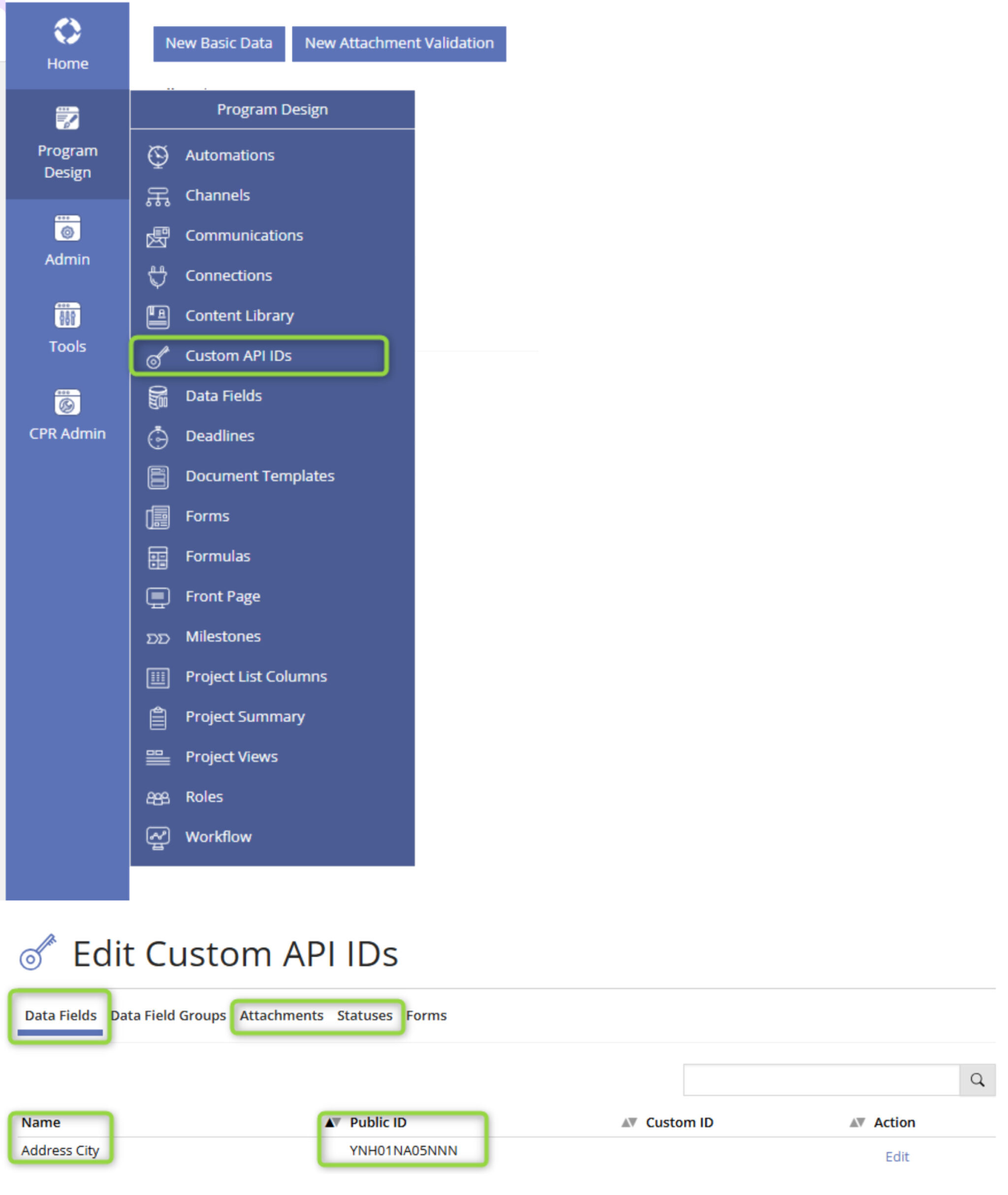
The table below designates what specific data fields, attachment form elements, and status’ need Custom IDs:
| Data Field | Custom ID |
|---|---|
| Circuit | Circuit |
| Impacts Exceeded | DRIVEImpacts |
| Within Hosting Capacity | WithinHostingCapacity |
| Attachment | |
| Hosting Capacity Summary | DRIVESummary |
| Status | |
| DRIVE Analysis Failed | DRIVEAnalysisFailed |
| DRIVE Analysis Results | DRIVEAnalysisResults |
7. Starting the DRIVE Connect Service
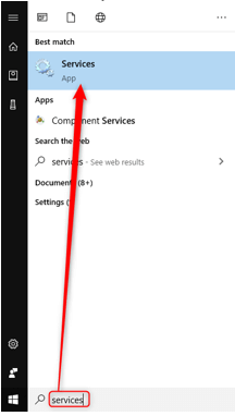
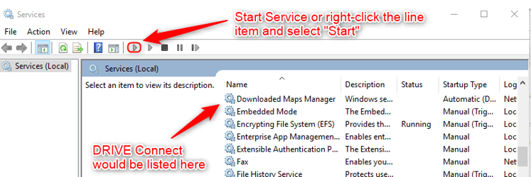
DRIVE Connect is a Windows Service and not an application. To use DRIVE Connect, the user must start the service from the Services menu. To find the services menu, either search for ‘Service’ in the Windows Search bar, or navigate to the Services menu from the Control Panel by selecting System and Security>Administrative Tools>Services. Select DRIVE Connect from the list of services and click on the green ‘Start Service’ button, or right click and select ‘Start’ from the drop-down menu:
8. Using the DRIVE Connect Service
Once the DRIVE Connect service has been started the user can request hosting capacity analysis for a project by changing the project status to DRIVE Analysis Requested from PowerClerk. DRIVE Connect will find the project and perform the hosting capacity analysis during the next search at the specified run interval as described above:

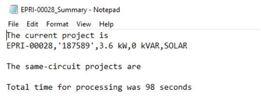
When the analysis is finished a new folder with the name of the project will be created in the Interconnection_Requests directory. This folder contains a copy of the original DRIVE input files with the DER described in the project as well as any same circuit project DERs in the _buses.csv file. The hosting capacity results are also stored in this folder. Along with the DRIVE input files and DRIVE results files, a summary text file is also created containing the details of the analysis. The summary text file lists the details of the current project.
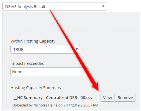
If the analysis completed successfully the project status will be changed to DRIVE Analysis Results. At this point the project engineer can use the hosting capacity results to continue processing the interconnection application. Details from the analysis can be found in the DRIVE Analysis Results form. If the circuit has remaining hosting capacity (>0.0 MW) for the selected impact factors, the Within Hosting Capacity field is set to TRUE, otherwise this field is set to FALSE and the selected impacts with zero remaining hosting capacity are displayed in the Impacts Exceeded field. The hosting capacity summary report is attached in the Hosting Capacity Summary field.

If the analysis was not completed successfully the project status will be changed to DRIVE Analysis Failed. There are a variety of reasons that could cause the analysis to not complete successfully. If DRIVE Connect is not able to launch DRIVE via the batch script described above the analysis will not be completed. This issue can be tested by placing a set of DRIVE input files in the Interconnection_Requests directory, followed by manually executing the batch script.
If the Circuit and Node described in the Engineering Review Project Data Form cannot be matched to a location within the DRIVE input files then the summary text file will indicate an error and the project status will be set to DRIVE Analysis Failed. The Circuit and Node information would be in the DRIVE Connect.exe.config file, which is defined by the DRIVEInputFilePath key. If one of the same circuit projects cannot be located in the appropriate DRIVE input file the error will be indicated in the summary text file, but the analysis will continue.
FAQs
Have additional questions? Contact us to nominate your FAQ and help others find answers to your own questions concerning this feature.
Contribute To A PowerClerk Integration Guide
Would you like to see a integration guide about a specific subject or contribute your experiences to share them with other PowerClerk Administrators? Contact the PowerClerk Support Team and propose a new integration guide at the PowerClerk Ticket System.
Create A Support Ticket
Not finding your answer here? Submit a question to our support team at the PowerClerk Ticket System and leverage the PowerClerk team’s expertise.